- 您现在的位置:买卖IC网 > Sheet目录337 > LT3466EDD#PBF (Linear Technology)IC LED DRIVR WHITE BCKLGT 10-DFN
LT3466
APPLICATIO S I FOR ATIO
Table 3. Inrush Peak Current
Using a DC Voltage
V IN (V)
5
5
5
5
9
12
L ( μ H)
15
33
47
68
47
33
C OUT ( μ F)
0.47
1.00
2.2
1.00
0.47
0.22
I P (A)
0.78
0.77
0.95
0.53
0.84
0.93
For some applications, the preferred method of brightness
control is a variable DC voltage to adjust the LED current.
The CTRL pin voltage can be modulated to set the dimming
of the respective LED string. As the voltage on the CTRL
pin increases from 0V to 1.6V, the LED current increases
from 0 to I LED . As the CTRL pin voltage increases beyond
1.6V, it has no effect on the LED current.
Typically peak inrush current will be less than the value
calculated above. This is due to the fact that the DC
resistance in the inductor provides some damping result-
ing in a lower peak inrush current.
PROGRAMMING LED CURRENT
The LED current of each LED string can be set indepen-
dently by the choice of resistors R FB1 and R FB2 respec-
tively (Figure 2). The feedback reference is 200mV. In
order to have accurate LED current, precision resistors are
preferred (1% is recommended).
The LED current can be set by:
I LED ≈ (200mV/R FB ), when V CTRL > 1.6V
I LED ≈ (V CTRL /5 ? R FB ), when V CTRL < 1V
Feedback voltage variation versus control voltage is given
in the Typical Performance Characteristics graphs.
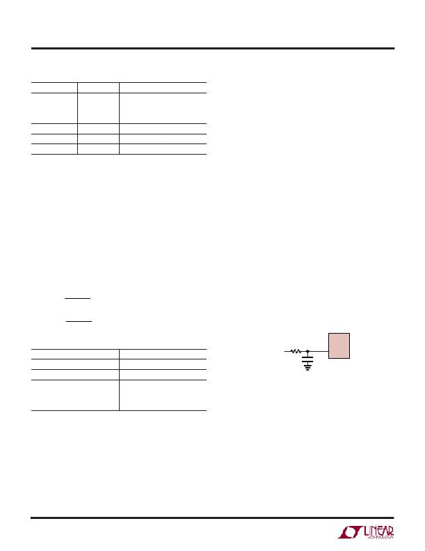
Using a Filtered PWM Signal
A variable duty cycle PWM can be used to control the
brightness of the LED string. The PWM signal is filtered
(Figure 8) by an RC network and fed to the CTRL1, CTRL2
pins.
R FB 1 =
R FB 2 =
200 mV
I LED 1
200 mV
I LED 2
The corner frequency of R1, C1 should be much lower than
the frequency of the PWM signal. R1 needs to be much
smaller than the internal impedance in the CTRL pins,
which is 100k ? .
Table 4. R FB Value Selection
I LED (mA)
5
R FB ( ? )
40.2
PWM
10kHz TYP
R1
10k
C1
1 μ F
LT3466
CTRL1,2
3466 F08
10
20.0
15
20
25
13.3
10.0
8.06
Figure 8. Dimming Control Using a Filtered PWM Signal
LOW INPUT VOLTAGE APPLICATIONS
Most White LEDs are driven at maximum currents of
15mA to 20mA.
DIMMING CONTROL
There are two different types of dimming control circuits.
The LED current in the two drivers can be set indepen-
dently by modulating the CTRL1 and CTRL2 pins
The LT3466 can be used in low input voltage applications.
The input supply voltage to the LT3466 must be 2.7V or
higher. However, the inductors can be run off a lower
battery voltage. This technique allows the LEDs to be
powered off two alkaline cells. Most portable devices have
a 3.3V logic supply voltage which can be used to power the
LT3466. The LEDs can be driven straight from the battery,
resulting in higher efficiency.
respectively.
3466fa
12
发布紧急采购,3分钟左右您将得到回复。
相关PDF资料
LT3474IFE#PBF
IC LED DRVR HP CONS CURR 16TSSOP
LT3475EFE-1#PBF
IC LED DRVR HP CONS CURR 20TSSOP
LT3476EUHF#PBF
IC LED DRVR HP CONST CURR 38-QFN
LT3477EFE#PBF
IC LED DRVR HP CONS CURR 20TSSOP
LT3478IFE#PBF
IC LED DRVR HP CONS CURR 16TSSOP
LT3486EFE#PBF
IC LED DRVR WHITE BCKLGT 16TSSOP
LT3491EDC#TRMPBF
IC LED DRIVER WHITE BCKLGT 6-DFN
LT3492IFE#TRPBF
IC LED DVR HP CONST CURR 28TSSOP
相关代理商/技术参数
LT3466EDD#PBF
制造商:Linear Technology 功能描述:LED DRIVER BOOST PWM 1MHZ 制造商:Linear Technology 功能描述:LED DRIVER, BOOST, PWM, 1MHZ, DFN-10
LT3466EDD#TR
功能描述:IC LED DRIVR WHITE BCKLGT 10-DFN RoHS:否 类别:集成电路 (IC) >> PMIC - LED 驱动器 系列:- 标准包装:6,000 系列:- 恒定电流:- 恒定电压:- 拓扑:开路漏极,PWM 输出数:4 内部驱动器:是 类型 - 主要:LED 闪烁器 类型 - 次要:- 频率:400kHz 电源电压:2.3 V ~ 5.5 V 输出电压:- 安装类型:表面贴装 封装/外壳:8-VFDFN 裸露焊盘 供应商设备封装:8-HVSON 包装:带卷 (TR) 工作温度:-40°C ~ 85°C 其它名称:935286881118PCA9553TK/02-TPCA9553TK/02-T-ND
LT3466EDD#TRPBF
功能描述:IC LED DRIVR WHITE BCKLGT 10-DFN RoHS:是 类别:集成电路 (IC) >> PMIC - LED 驱动器 系列:- 标准包装:6,000 系列:- 恒定电流:- 恒定电压:- 拓扑:开路漏极,PWM 输出数:4 内部驱动器:是 类型 - 主要:LED 闪烁器 类型 - 次要:- 频率:400kHz 电源电压:2.3 V ~ 5.5 V 输出电压:- 安装类型:表面贴装 封装/外壳:8-VFDFN 裸露焊盘 供应商设备封装:8-HVSON 包装:带卷 (TR) 工作温度:-40°C ~ 85°C 其它名称:935286881118PCA9553TK/02-TPCA9553TK/02-T-ND
LT3466EDD-1
制造商:Linear Technology 功能描述:LED DRVR 10Segment 3.3V/5V/9V/12V/15V/18V 10-Pin DFN EP
LT3466EDD-1#PBF
功能描述:IC LED DRIVR WHITE BCKLGT 10-DFN RoHS:是 类别:集成电路 (IC) >> PMIC - LED 驱动器 系列:- 标准包装:60 系列:- 恒定电流:- 恒定电压:- 拓扑:线性(LDO),PWM,升压(升压) 输出数:8 内部驱动器:是 类型 - 主要:背光 类型 - 次要:RGB,白色 LED 频率:500kHz ~ 1.5MHz 电源电压:4.75 V ~ 26 V 输出电压:45V 安装类型:* 封装/外壳:* 供应商设备封装:* 包装:* 工作温度:-40°C ~ 85°C
LT3466EDD-1#PBF
制造商:Linear Technology 功能描述:IC, LED DRVR, DFN10
LT3466EDD-1#TRPBF
功能描述:IC LED DRIVR WHITE BCKLGT 10-DFN RoHS:是 类别:集成电路 (IC) >> PMIC - LED 驱动器 系列:- 标准包装:6,000 系列:- 恒定电流:- 恒定电压:- 拓扑:开路漏极,PWM 输出数:4 内部驱动器:是 类型 - 主要:LED 闪烁器 类型 - 次要:- 频率:400kHz 电源电压:2.3 V ~ 5.5 V 输出电压:- 安装类型:表面贴装 封装/外壳:8-VFDFN 裸露焊盘 供应商设备封装:8-HVSON 包装:带卷 (TR) 工作温度:-40°C ~ 85°C 其它名称:935286881118PCA9553TK/02-TPCA9553TK/02-T-ND
LT3466EDDPBF
制造商:Linear Technology 功能描述:Dual Full Func White LED contrlr,LT3466
